Gray vertical rectangular pattern with several clusters of small white dots arranged in rounded organic shapes scattered.

PlantGraph

Your whole plant, finally connected.

PlantGraph is one model of your entire plant: every piece of equipment, every connection, and everything your teams know. Here’s how it works, start to finish.


Industrial process flow diagram on a software interface showing three interconnected sections labeled 2024-NFLD-0419, 2024-NFLD-0418, and 2024-NFLD-0425, with colored lines (orange, green, pink, purple, blue) tracing flow paths between various equipment and valves. The right side panel displays details for equipment C-210, including unit classification and connected major equipment, with color-coded listings for E-211A (red), V-210 (green), P-210B (blue), and P-210A (orange). The interface has a search bar at the top, menu options for groups, systems, LOTO, major equipment, line numbers, QA, and alarms, and multiple navigation icons along the left and bottom edges.
Vertical dark grey panel with clusters of small white dots forming irregular, rounded shapes arranged sparsely across the panel.
A horizontal row of small white dots evenly spaced, creating a minimalist divider pattern.

Today, your plant lives in drawings, a historian, a maintenance system and a stack of spreadsheets. With PlantGraph, it lives in one model.

Create

One connected plant model of your facility.

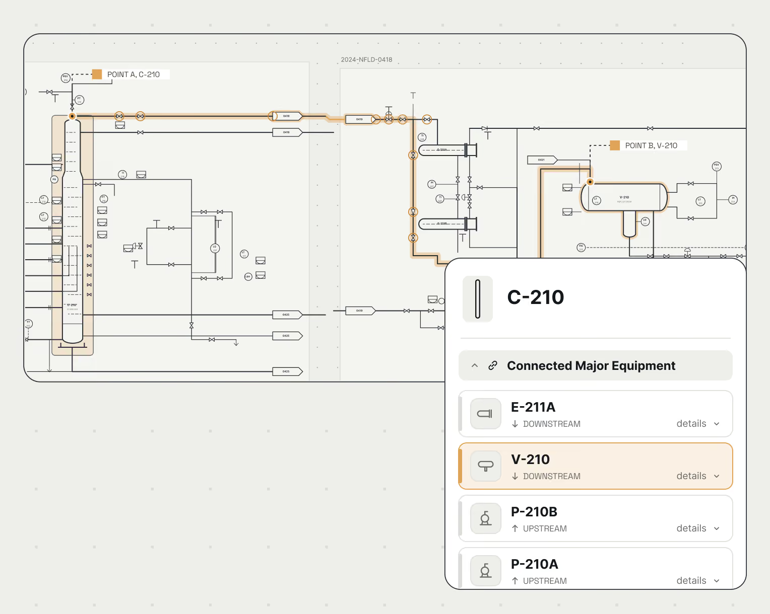
Built from the schematics you already own, including decades of brownfield drawings. PlantGraph builds a complete flow representation of your facility from beginning to end, down to every flange, so you know where every piece of equipment is, what it connects to upstream and downstream and how it functions within your plant.

Import your brownfield schematics.

Bring in legacy schematics as they are, in the DXF and DWG files you already have, with no redrafting and no new data collection.

Built by algorithms, checked by engineers.

Every symbol, line and valve is detected automatically, then reviewed by engineers. Real-world schematics hold ambiguity that takes an expert to resolve, and your most critical workflows demand the highest quality.

Connected with flow end-to-end.

Navigate paths throughout the facility, understand what lies along them, and visualize what you need to do your job.
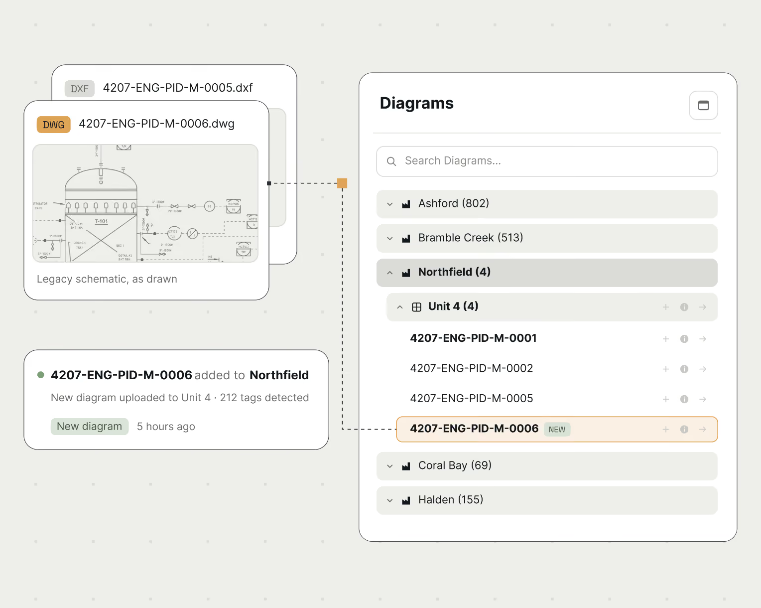
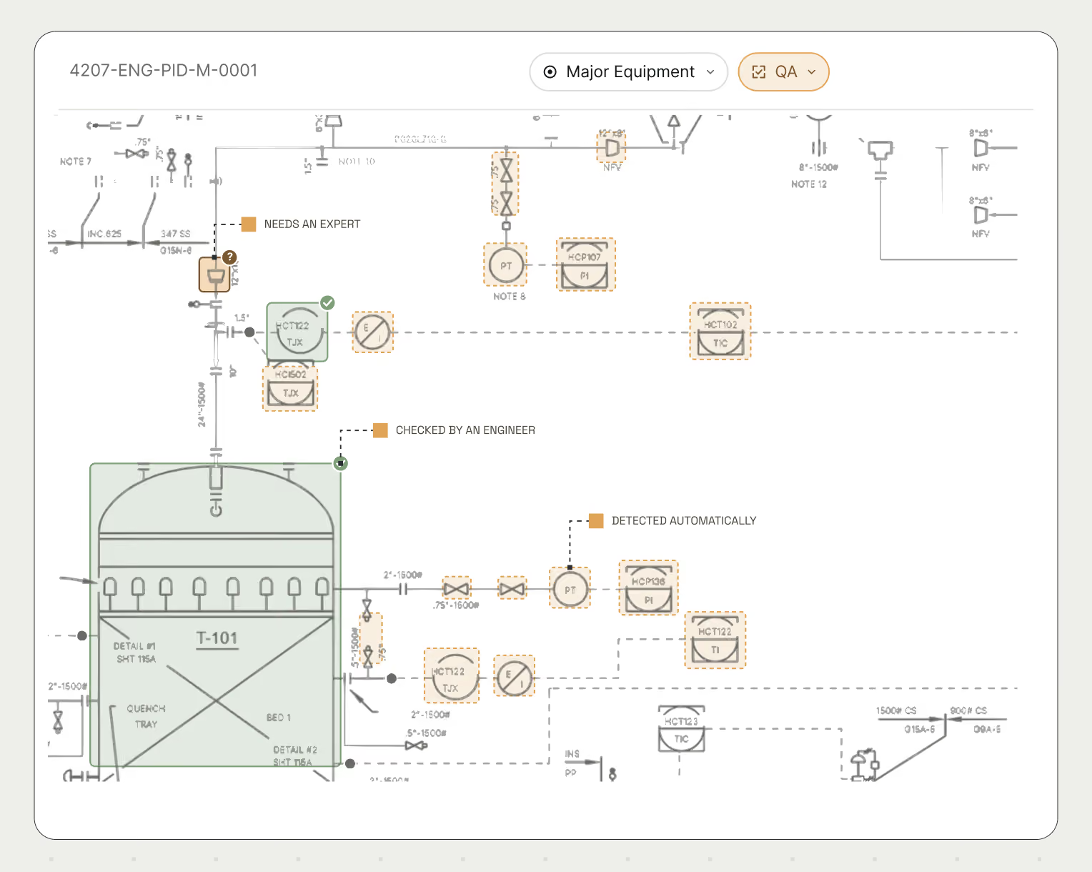
User interface showing a diagram library with folders named Ashford, Bramble Creek, Northfield, Coral Bay, and Halden, each with item counts. The Northfield folder is expanded, revealing Unit 4 with four diagrams. Diagram 4207-ENG-PID-M-0006 is labeled new and highlighted. A preview panel shows a legacy schematic labeled 4207-ENG-PID-M-0006.dwg with annotations. A notification states that diagram 4207-ENG-PID-M-0006 was added to Northfield 5 hours ago with 212 tags detected. Search functionality is present at the top.Engineering schematic diagram showing equipment T-101, valves, sensors, and control instrumentation, with annotations for needs an expert, checked by an engineer, and detected automatically.Technical flow diagram showing equipment connections with a highlighted pipeline path linking POINT A, C-210 to POINT B, V-210, alongside a panel listing connected major equipment including E-211A and V-210 downstream, and P-210B and P-210A upstream.

Enrich

Add what your systems and people know.

Layer governed engineering knowledge anchored to the equipment that it describes.  Once something is added, everyone can find it.

Classify equipment.

Group the equipment you manage together, like systems or corrosion circuits, so every team works from the same definitions.

Codify human knowledge.

Turn a traced route into a piping circuit or map a control loop in a few clicks.

Bring in existing data.

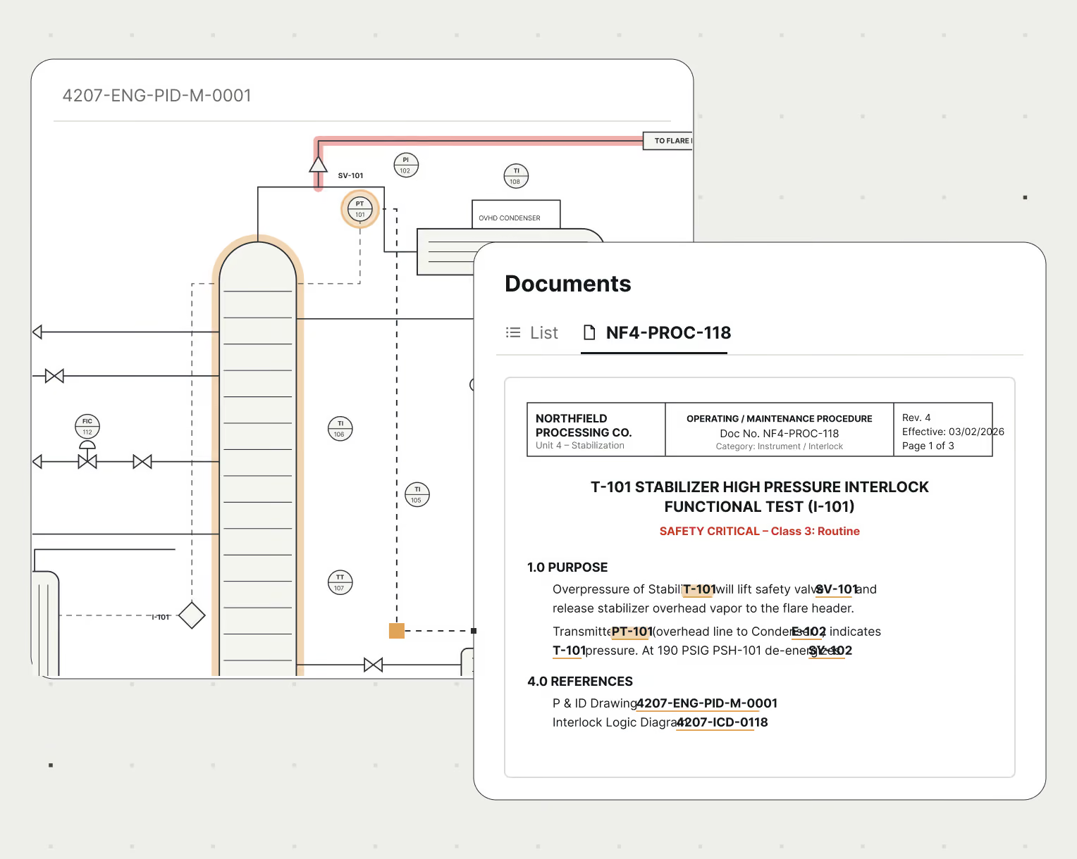
Easily attach operating procedures, spec information, inspection data, work orders, etc. to the equipment they belong to using the model itself.
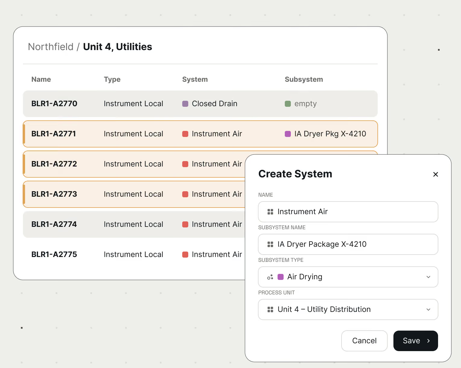
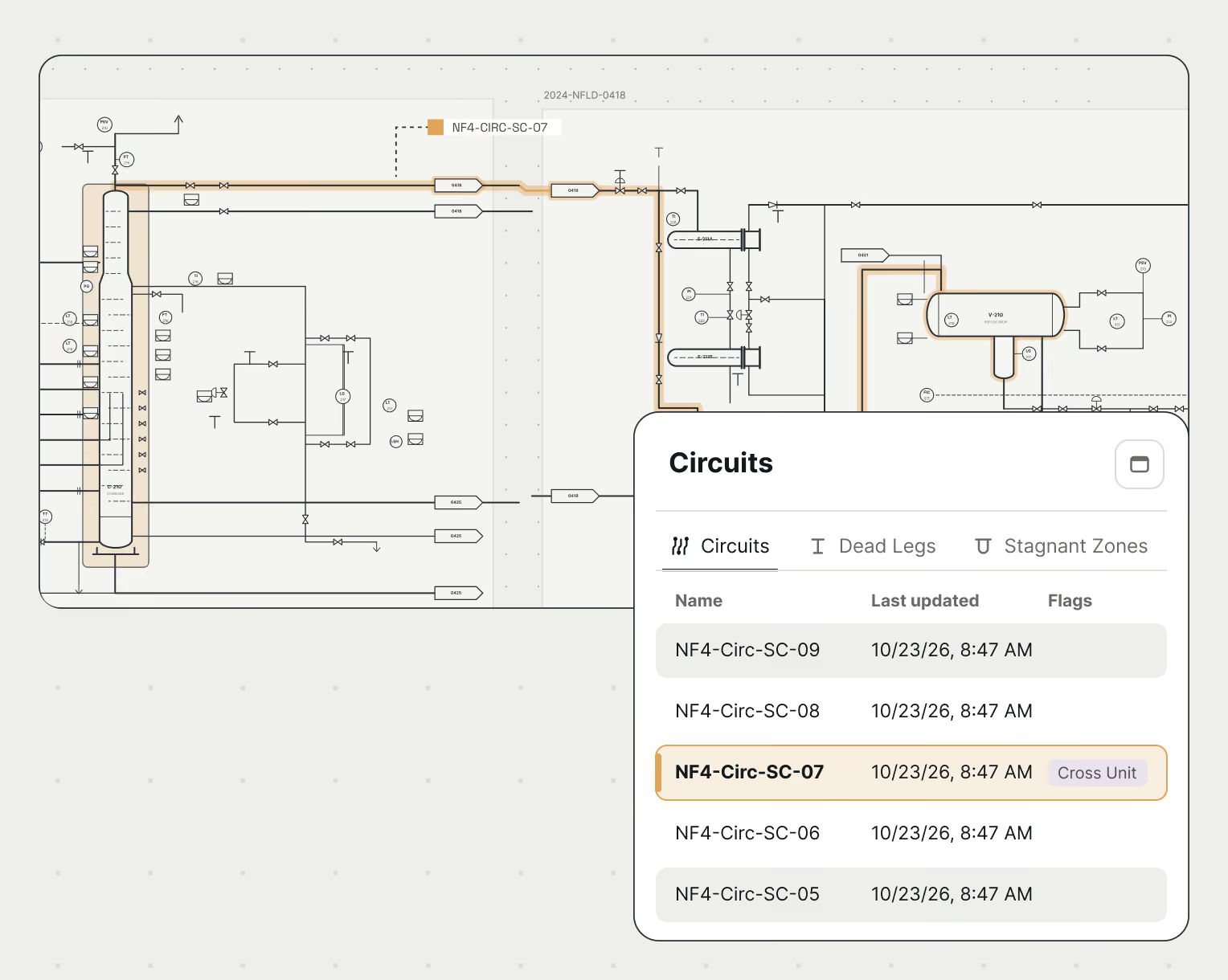
User interface showing a table titled 'Northfield / Unit 4, Utilities' listing equipment with columns for Name, Type, System, and Subsystem. Several items labeled BLR1-A2770 to BLR1-A2775 are shown with Instrument Local type and mostly Instrument Air system. Highlighted row BLR1-A2771 has a subsystem IA Dryer Pkg X-4210. A 'Create System' popup dialog overlays the table with fields for Name (Instrument Air), Subsystem Name (IA Dryer Package X-4210), Subsystem Type (Air Drying), and Process Unit (Unit 4 – Utility Distribution), plus Cancel and Save buttons.Technical diagram showing a complex circuit with pipes and valves, highlighting circuit NF4-Circ-SC-07 in orange. A panel on the right lists circuit names, last updated timestamps, and flags, with NF4-Circ-SC-07 marked 'Cross Unit' and highlighted.Partial technical process diagram showing equipment and piping with labels and symbols; overlay of a digital document titled 'T-101 Stabilizer High Pressure Interlock Functional Test (I-101)' from Northfield Processing Co., detailing safety critical test procedures, purpose, and references tied to drawing 4207-ENG-PID-M-0001, with key terms like SV-101, PT-101, and 4207-ICD-0118 highlighted.

Sustain

Kept current with every change.

Plants change every day. PlantGraph keeps the model current, along with everything your teams have added to it.

Unify updates.

When the plant changes, its diagrams, systems, circuits and instrument loops all update with it.

Versioned and traceable.

Every change is tracked, so you can see what changed, when and why, with the ability to resolve conflicts coming soon.

Always current.

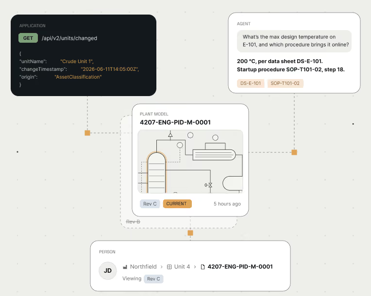
Every application, agent, or person using PlantGraph gets the facility model as it is today, not an outdated drawing.
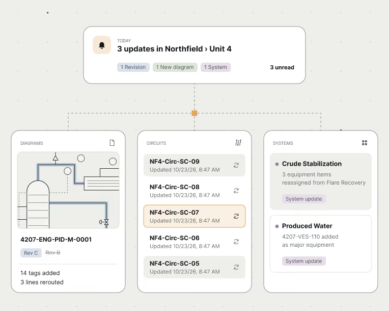
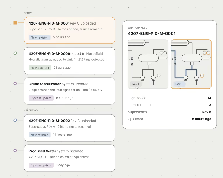
User interface showing 3 updates in Northfield Unit 4: 1 Revision, 1 New diagram, 1 System, with 3 unread notifications. Below, three panels labeled Diagrams, Circuits, and Systems list specific updates including a diagram with 14 tags added and 3 lines rerouted, circuits NF4-Circ-SC-09 to SC-05 updated on 10/23/26 at 8:47 AM, and system updates for Crude Stabilization and Produced Water with specific equipment changes.Timeline of updates and revisions for engineering documents and system updates showing entries for today and yesterday. Highlights include document 4207-ENG-PID-M-0001 Rev C uploaded 5 hours ago with 14 tags added and 3 lines rerouted, and system updates such as Crude Stabilization and Produced Water with related notes on equipment and tag changes. On the right, comparison diagrams of document 4207-ENG-PID-M-0001 show changes between Rev B and Rev C with counts of tags added (14) and lines rerouted (3).Diagram showing interconnected elements: an API GET request for '/api/v2/units/changed' with JSON data about 'Crude Unit 1' and timestamp, a chat agent responding about max design temperature and startup procedure for equipment E-101, a plant model labeled 4207-ENG-PID-M-0001 marked current revision C, and a user interface section showing a person labeled JD viewing the same plant model in Unit 4 at Northfield.

Explore

Find in minutes what used to take days.

Search your entire plant the way you’d search the web, with every answer in the context of the equipment and flow around it.

Find anything.

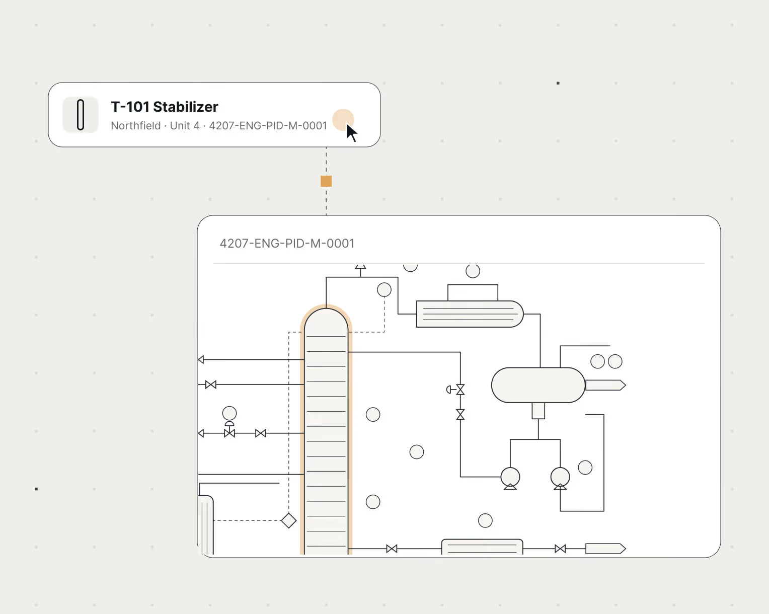
Type a tag and get the equipment, its details, its documents, and where it sits in the process.

Understand relationships.

Answer questions only a connected model can, like every pressure vessel, its nearest relief valve, and that valve’s set pressure.

Explore your facility.

Navigate between any two locations in your plant, explore what’s near and between them, break the constraints of traditional drawings.
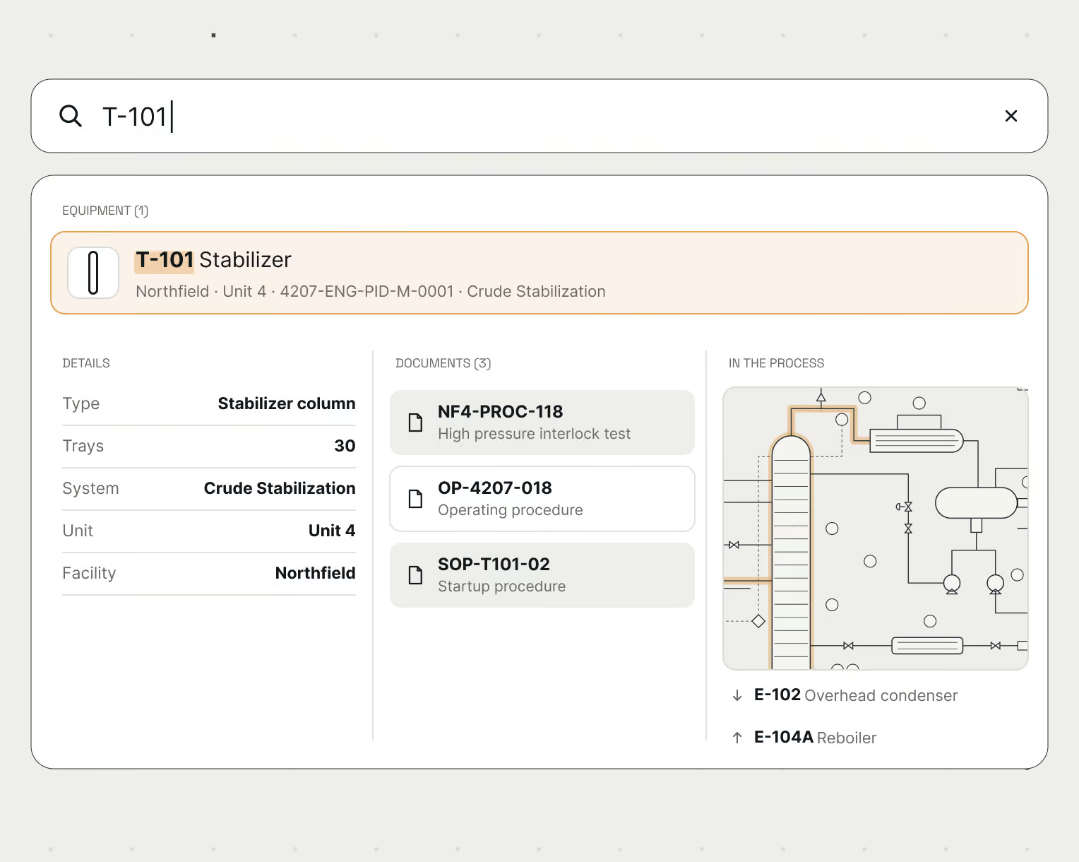
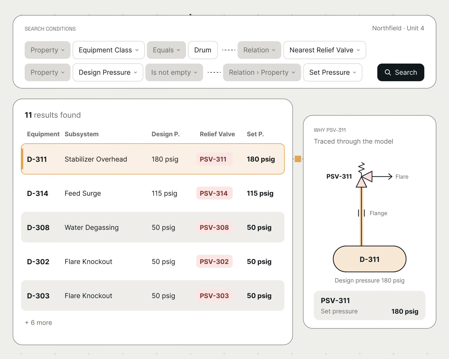
User interface search results for equipment T-101 Stabilizer, showing details including type as Stabilizer column, 30 trays, system Crude Stabilization, unit 4, facility Northfield. Documents listed are NF4-PROC-118 for high pressure interlock test, OP-4207-018 operating procedure, and SOP-T101-02 startup procedure. A simple process diagram on the right highlights related equipment E-102 Overhead condenser and E-104A Reboiler.Interface of an advanced search tool filtering for equipment class 'Drum' and nearest relief valve set pressure. The search results list 11 items, showing equipment with subsystems, design pressure, relief valves, and set pressures. Highlighted is equipment D-311, Stabilizer Overhead, with design pressure 180 psig and relief valve PSV-311 set at 180 psig. A schematic on the right traces relief valve PSV-311 through the model, showing connection to D-311 with a flare and flange, indicating design pressure 180 psig and set pressure 180 psig for PSV-311.Technical schematic diagram labeled 4207-ENG-PID-M-0001 shows interconnected equipment and pipelines with a highlighted vertical stabilizer column on the left, titled 'T-101 Stabilizer' with unit and tag details above it.

Integrate

Get more out of your existing applications.

Your applications, analytics and AI work from a model that represents your facility with every analysis and decision captured for future re-use.

Open APIs and SDKs.

Serve the plant model to the systems, apps, and agents your teams already run to get more out of your existing investments.

Connect your LLM.

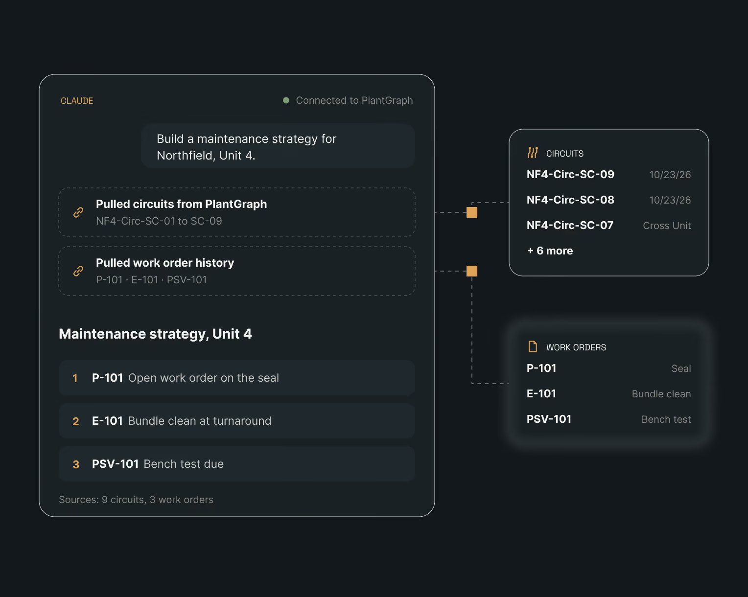
Ask your LLM for a maintenance strategy and it pulls the circuits, work order history, and plant visualization from PlantGraph, then builds the plan on top.

Permissions carried along.

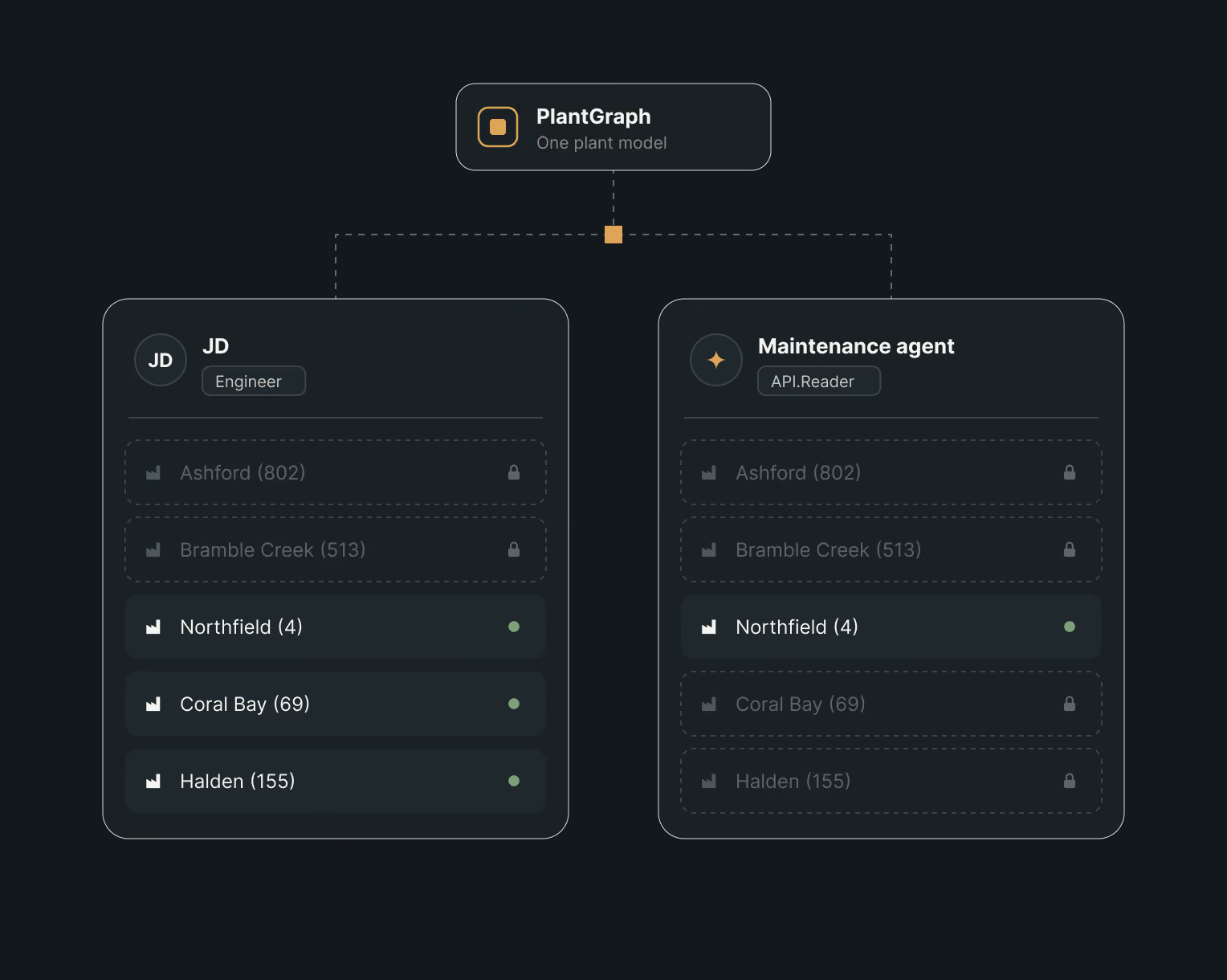
People and agents only see what they’re allowed to see.
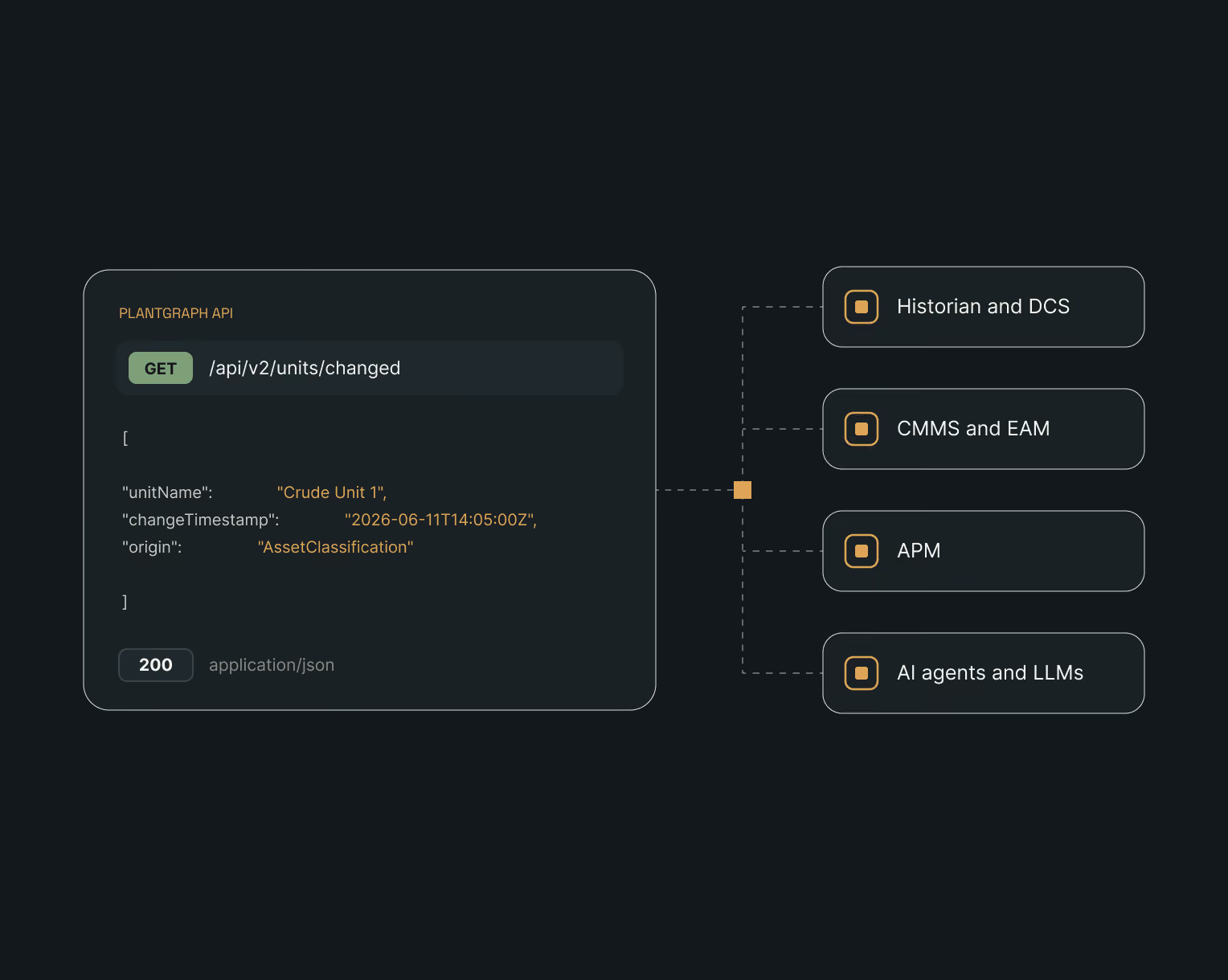
Diagram showing a PlantGraph API GET request to /api/v2/units/changed returning JSON data with fields unitName 'Crude Unit 1', changeTimestamp '2026-06-11T14:05:00Z', and origin 'AssetClassification', with a 200 status code, connected by a flow to four components labeled Historian and DCS, CMMS and EAM, APM, and AI agents and LLMs.Dashboard interface showing a maintenance strategy for Northfield, Unit 4, with pulled circuits and work order history from PlantGraph, listing circuits NF4-Circ-SC-01 to SC-09 and work orders P-101, E-101, PSV-101 including tasks like seal opening, bundle cleaning, and bench testing.Diagram showing PlantGraph labeled as one plant model connected to two sections: JD, an engineer, and Maintenance agent, an API reader. Both have lists of locations with numbers in parentheses; Ashford (802) and Bramble Creek (513) are locked and grayed out. JD has Northfield (4), Coral Bay (69), and Halden (155) highlighted with green indicators, while Maintenance agent has only Northfield (4) accessible with green indicator, others locked.

Compliance

Trusted by industry leaders.

SOC 2 certified and deployable where your data sits: on-prem, in your private cloud, or hosted by us. PlantGraph connects to your existing data stack through open APIs, with role-based access and SSO to control who sees what.

Seal with AICPA at the top inside a blue arc, a grey horizontal band with SOC in black letters, and a black semi-circle below with the URL aicpa.org/soc; text to the right reads SOC 2 TYPE II CERTIFIED in blue capital letters with CERTIFIED underlined.

Your plant model is yours, open by design and always exportable.